Development of precision optical surfaces demands the use of sub-aperture polishing methods in order to obtain specific figure and surface finish. Precise characterization of figure errors, which define the qualification of mid spatial frequency marks left by the tool path, are needed for low-cost fabrication. Such fabrications place significant demands on a metrology system, such as superior imaging fidelity against frequency utilizing an instrument transfer function to measure performance, and large slope acceptance with reduced rigid-body retrace.
The metrology space covers spherical, plano and mild aspheric optical surfaces that range from 25 mm up to several meters in diameters. Phase-shifting interferometry is the preferred metrology for optical testing in controlled environments, while instantaneous interferometers are needed for complex environments.

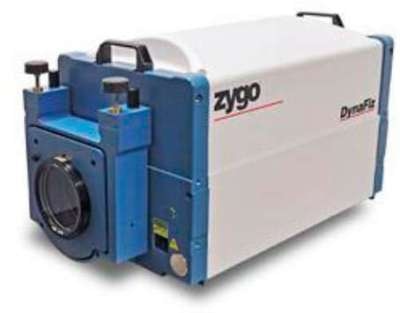
Figure 1. ZYGO DynaFiz dynamic interferometer.
An assessment of retrace and instrument transfer function performance is provided for an interferometer, which is capable of both instantaneous interferometry and phase-shifting interferometry utilizing carrier fringes for linear spatial phase shifting.
The design of the instrument improves the balance between lateral resolution and high-speed measurements for data acquisition techniques. This application note provides an overview of how lateral resolution and slope acceptance are related, how an optically coherent zoom system supports single-frame metrology of spatial frequencies further than 9.0 cycles/mm, and how carrier fringe techniques for immediate measurements can be improved for lateral resolution.
Instrument Slope Acceptance
Present generation of interferometers employ digital electronic cameras to use sophisticated computing power for processing interferograms. Through separate sampling by these sensors, the fundamental imaging resolution limits are established at the detector plane, and offers performance and design targets for lateral resolution and slope acceptance as a function of imaging magnification. Slope acceptance of an instrument is associated with the tilt angle between test wavefronts and interfering reference, producing unvignetted fringes at the detector plane with period equivalent to the specified maximum spatial frequency. When the noise is reduced, it might drive the targeted resolution to some fraction of Nyquist, for instance 0.9. These factors include preventing the detection of higher frequency aliased fringes, restraining diffracted reflections from the sensor array, and controlling the energy passed from unnecessary reflections across the system.
High Slopes and Retrace Error
While developing a system for high slopes, lens design is required to reduce retrace error, in addition to meticulous matching of system aperture and camera resolution. This is especially critical in spatial phase shifting techniques that depend on carrier fringes produced by introducing a tilt offset between the reference surfaces and object, leading to a fringe density as high as ½ Nyquist.
Lateral Resolution with Dynamic Interferometry

Figure 2. Acquired interferogram sub-regions illustrating carrier fringes aligned for maximum lateral resolution in the Y direction (left), the X direction (middle), and along the diagonal (right). The resolution cutoff frequency is increased by the square root of 2 for the diagonal orientation corresponding to 420 cycles/aperture over a 1200x1200 pixel camera.
The limitations of the carrier fringe technique can be understood by contemplating what happens to the spatial phase shift with increasing tilt. Let us assume a minimal fringe density of ½ Nyquist or 4 pixels/fringe (PPF). If the fringes are tilted in one way, it can be up to Nyquist before we attain the limit implied by aliasing, and if we tilt the other way, we can reach as far as null. Both directions are ± the number of fringes over the aperture, and as a result the cutoff frequency in cycles/aperture is equivalent to the fringe density in fringes/aperture. Therefore, for a 1200x1200 camera, there is a resolution cutoff frequency of 300 cycles/aperture along the x and y axes. Moreover, it is not essential to have a sharp decline in instrument response at the cutoff frequency, since this can produce ripple artifacts, termed as Gibbs phenomenon, in the last three-dimensional profile. Instead, it is better to make a steady attenuation of the instrument response as a function of frequency, so that the cutoff frequency denotes a reduced response instead of a hard limit.
ZYGO's DynaFiz™ Dynamic Laser Interferometer for Precision Metrology in Less Than Ideal Environments
In order to off-set lateral resolution limits and possible errors in the phase calculation, design compromises are needed of all single-frame algorithms to promote a convergence in instrument transfer function behavior between carrier fringes and other techniques, which are based on spatial phase shifting.
Although pixelated camera interferometers and carrier fringe may report non-zero instrument transfer function further than ½ Nyquist, there are practical questions about the effectiveness of any spatial frequency data at these high frequencies. The reason is that the frequencies identified close to Nyquist could relate to aliased data induced by coupling with the spatial phase shift frequency.

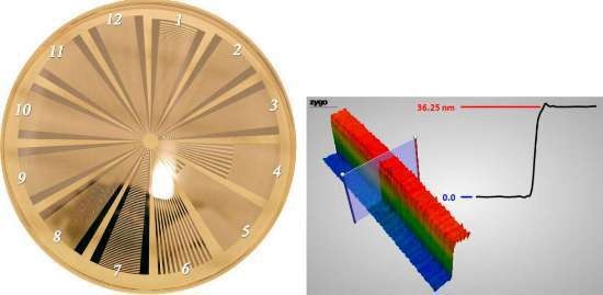
Figure 3. Photo of the Ø 100mm custom periodic artifact, after photolithography process and wet etch, but before final chromium layer was applied for uniform reflectivity.
Conclusion
Metrological integrity of mid spatial frequency as well as low-order figure is needed for fabrication of modern precision optical surfaces where sub-aperture polishing method is being widely used to suit complex demands. Majority of these optical surfaces warrant testing within environments where single-frame instantaneous interferometry offers the only viable solution.

This information has been sourced, reviewed and adapted from materials provided by Zygo Corporation.
For more information on this source, please visit Zygo Corporation.