Optical filters are key components in various industrial and scientific applications. Their capacity to manipulate light waves to extract specific wavelengths or block unwanted frequencies is central to microscopy, spectroscopy, laser systems, astronomical instrumentation, and many other settings.
The effectiveness of optical filters depends upon their precise alignment, and ensuring their proper orientation is imperative to achieving peak performance. Misalignment can lead to compromised results, negatively impacting measurement accuracy, image clarity, or process efficiency. Ensuring the proper orientation of optical filters is critical in attaining optimal performance.
Note: The information provided in this article is based on the standard catalog parts and sizes offered by Chroma Technology.
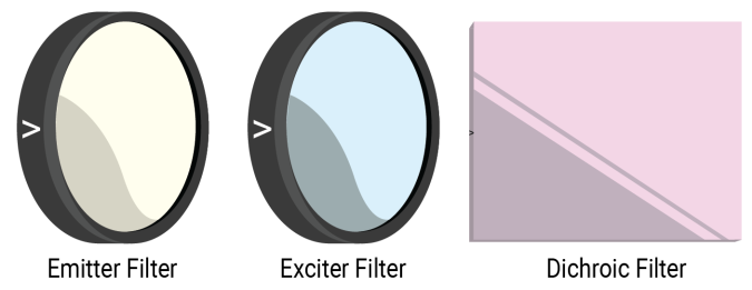
Image Credit: Chroma Technology Corp.
Orientation for Fluorescence Applications
Properly orienting the filter can minimize autofluorescence and maximize performance. Each filter features a caret/arrow on its edge to assist in this orientation.
The three primary optical filter components employed in fluorescence microscopy are the excitation filter, the emission filter, and the dichroic mirror or beamsplitter.
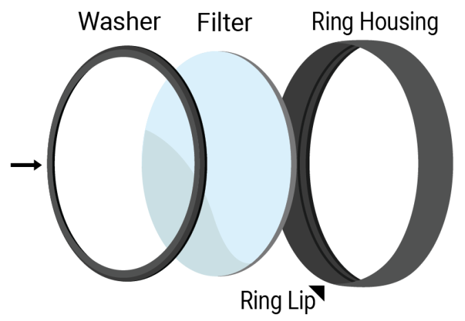
Image Credit: Chroma Technology Corp.
Filter Types
Excitation Filters
The arrow in excitation (x) filters points in the direction the light travels, so these filters must be positioned with the arrow pointing away from the light source, toward the specimen and the inside of the cube. Incorrect positioning can lead to increased background levels due to autofluorescence.
Emission Filters
Emission (m) filters must be situated with the arrow pointing away from the detector/eye, toward the specimen and the inside of the cube. If these filters are placed incorrectly, they may not sufficiently separate the emission signal from the excitation light, resulting in poor image contrast.
Dichroic Filters (Mirrors/Beamsplitters)
Dichroic mirrors or beamsplitters must be mounted with the primary coated surface pointed toward the light source, specimen, and excitation filters. This is indicated by the arrow on the side of the filter, which points to the primary coating. Incorrectly orienting these filters will change the position of the excitation light beam, potentially increasing background levels due to autofluorescence.
Image Credit: Chroma Technology Corp.
Orientation for Astronomy and Astrophotography Applications
Chroma Technology’s astronomy filters do not feature a caret, arrow, or other orientation marker. This is because the filter ensures peak performance regardless of which side faces the detector or light source.
Some users have reported slight variations in the filter’s effectiveness when using one side or another in their specific setups. However, it is likely that other variables in the optical system, such as the properties of the individual lenses, the light source, or the detector, are prompting this variability.
There should generally be no significant difference in performance, regardless of the filter orientation.
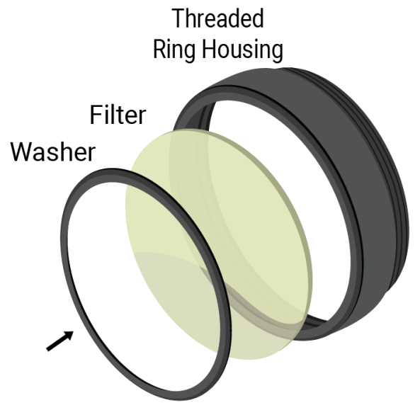
Image Credit: Chroma Technology Corp.
Orientation for Machine Vision Applications
The design of Chroma Technology’s optical filters means that their orientation is not linked to their performance when used for machine vision applications. These filters have been designed to ensure peak performance regardless of which side faces the detector or light source.
The filters’ primary bandpass coating is assembled against the ring lip, away from the washer side. This ensures consistency, ease of use, and uniformity across setups and is also a useful troubleshooting aid should any issues arise.
Acknowledgments
Produced from materials originally authored by Chroma Technology Corp.
This information has been sourced, reviewed, and adapted from materials provided by Chroma Technology Corp.