Each experimental "beamline" at free electron laser (XFEL) or synchrotron light facilities utilizes a series of bendable or fixed-curvature optics to efficiently direct and collimate ultra-intense X-Ray beams from their source to the target sample.1
The typical grazing angle of incidence required for the efficient total external reflection of X-Ray photons is a few milliradians. This, alongside the typical beam widths of a few millimeters, means that X-Ray mirrors are usually cuboids with lengths between 25 mm and 1500 mm and depths and widths in the range of 20 mm to 100 mm.
The optical face of the fused silica substrate or single-crystal silicon is pre-polished to fit a range of profiles, such as ellipses or cylinders, and frequently has a coating of metallic layers to improve X-Ray reflectivity.
The optical layout of each XFEL or synchrotron beamline is tailored to fit a range of experimental methods, such as combinations of spectroscopy, X-Ray diffraction, imaging, and ptychography.
Each beamline may be reconfigured to change multiple experimental parameters, such as X-Ray wavelength and the location or size of the focal spot.
Many optical communities have employed biomorph deformable mirrors for decades.2 Using feedback from a range of metrology sensors, these optics are typically operated in a closed loop with a refresh rate of hundreds or thousands of cycles per second.
However, tuning and stabilizing the surface of an X-Ray bimorph mirror is several orders of magnitude more difficult than that of visible light. This is because hard X-Rays (10 keV=0.124 nm) have a wavelength approximately 5000 times smaller than red light (633 nm).
Generally, the optical surface of an X-Ray mirror must be optimized for the desired profile with single-digit nanometer height errors.
Piezoelectric deformable bimorph X-Ray mirrors were first developed in the 1990s at the European Synchrotron Radiation Facility (ESRF) in France.3,4 They were then developed at Spring-8 in Japan,5 and subsequently commercialized by Thales-SESO in France.
X-Ray bimorphs are now utilized on many beamlines globally,6–8 and their achromatic nature enables beam-shaping control across a broad range of X-Ray wavelengths.
Over the recent decade, there has been an extensive collaborative research project9 to improve the performance of bimorph mirrors at Diamond Light Source (Diamond) - which is the UK’s national synchrotron radiation science facility.10
Mechanically bent mirrors typically require one or two independent bending motors11 and can only achieve elliptical or cylindrical profiles. Biomorph X-Ray mirrors, however, have extra degrees of bending freedom and zonal control (typically between 8 and 32 electrodes) which enables more sophisticated control of the optical surface and the reflected X-Ray wavefront.
This includes the correction of photon-induced heat bumps,12 optomechanical clamping of the mirror, residual polishing errors,13,14 thermal deformation caused by ambient temperature changes, and higher-order aberrations in the wavefront due to other imperfect optics in the same photon delivery system.15
A recent article16 gives a complete historical review of X-Ray optics, including the state-of-the-art wavefront preservation methods to accomplish diffraction-limited performance.
The significance of this subject is growing as numerous XFEL and synchrotron facilities upgrade their particle accelerators to create brighter and more coherent X-Ray beams.
Active X-Ray optics for XFEL and synchrotron beamlines have always been quasi-statically driven in open-loop mode. The shape of the profile of the mirror is only adjusted every few hours or days. In extreme instances, active mirrors remain unchanged for several months or years.
However, as X-Ray sources have become brighter, and detector technology and data processing have advanced, the sample throughput has increased significantly in recent years.
Many beamlines, especially those dedicated to macromolecular crystallography, routinely measure hundreds or even thousands of samples each day.
These beamlines now desire the rapid manipulation of the X-Ray beam’s shape and size, without loss of flux, to fit each crystal’s dimensions or to illuminate different-sized regions of larger samples.
There is an intrinsic constraint in quickly applying significant changes to the photo beam: when operated in open-loop mode, the curvature of X-Ray bimorph mirrors may drift by several percent over numerous hours after a large alteration in voltage.17 This results in a corresponding time variation in the shape and size of the reflected X-Ray beam.
Additionally, there is a substantial time lag between a change requested by the operator and the reaction of the complex system. These parasitic drifts will become increasingly challenging as facilities develop smaller, brighter X-Ray sources and utilize strong focusing geometries.
This motivates the development of a rapid, non-invasive, closed-loop “adaptive” bimorph system that is based on accurate nano-metrology feedback, which can make frequent and large adjustments to the X-Ray beam’s size.
It is also important that the closed-loop system should not attenuate or block the beam to maximize scientific usage of the X-Ray.
Materials and Methods
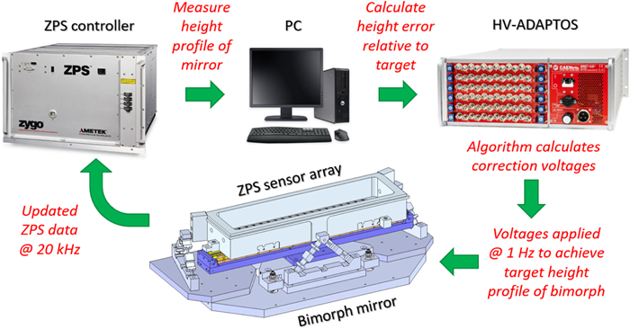
Fig. 1. Schematic diagram showing the main hardware components and procedures for autonomous closed-loop control of the bimorph X-Ray mirror at 1 Hz based on interferometric feedback. Image Credit: Zygo Corporation
System Overview
Figure 1 shows the primary components and the basic operational flow of the closed-loop X-Ray optical system.
This includes a piezoelectric bimorph deformable X-Ray mirror, a multi-sensor ZPS interferometer system that is mounted on an independently supported metrology frame by three bipod flexures, a programmable HVADAPTOS high-voltage (HV) bipolar power supply, a ZPS controller unit, and a personal computer (PC).
Bimorph Piezo Deformable X-Ray Mirror
The bimorph mirror is an early second-generation optical system that was first manufactured by Thales-SESO in 2013.18,19 The substrate has 16 piezo electrodes and is 640 mm in length.
In contrast to mechanically bent mirrors, bimorph mirrors can work continuously in ultra-high vacuum conditions without encountering any heating problems – as the piezo actuators only draw a few µA of current for short periods.
Alongside zonal control, this feature makes biomorph mirrors the perfect candidate for continuous, real-time, high-spatial resolution and adaptive correction of photon beams.
The mirror’s holder was specifically designed by S.RI.Tech, Italy, to minimize the mechanical strain imparted to the mirror.20 It was later manufactured by Strumenti Scientifici Cinel, Italy.20
Several studies have demonstrated that the long-term response of biomorph mirrors is linear: height changes induced in the optical surface via the application of voltage to individual piezo actuators can be used to accurately predict the global outcome of applying all such voltage changes simultaneously.
Assuming stable beamline conditions, a biomorph mirror, when subject to a set of piezo voltages, will asymptotically approach a repeatable, quasi-static state over several hours. Many beamlines utilize lookup tables to switch between focal positions when they infrequently bend the mirror.
However, the application of sizable and frequent changes leads to the mirror operating in a dynamic, non-equilibrium state. In this case, the optimum voltages needed to bend the mirror to a certain shape are dependent on the recent bending history of the substrate.
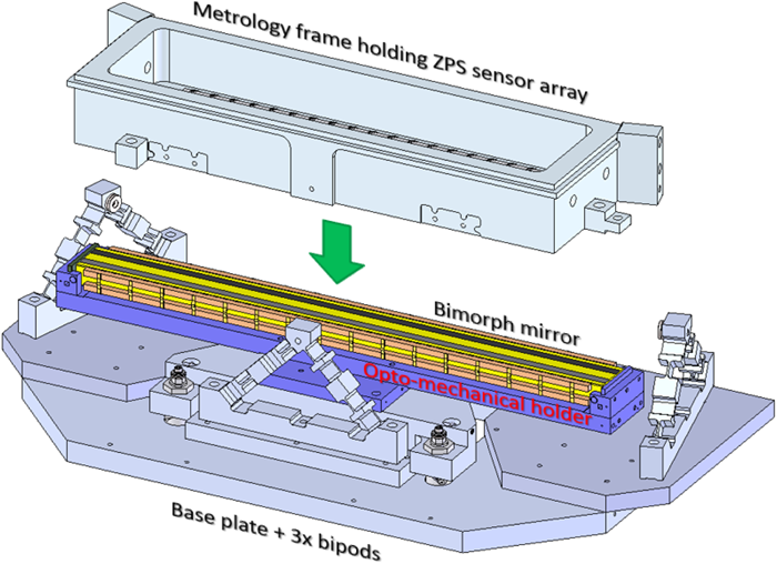
Fig. 2. Exploded view of the metrology frame and bimorph system. Bimorph mirror (yellow) is mounted into a holder (blue), which is attached to the base plate (dark gray) containing three bipod flexures. The metrology frame (light gray), holding an array of ZPS interferometric sensors, is mated with the three bipods. This arrangement securely holds the ZPS sensors ~3.5 mm above the optical surface of the bimorph mirror whilst allowing line-of-sight access for grazing angle of incidence X-Rays. The bipod flexures ensure that the metrology frame is largely insensitive to thermal changes and is decoupled from the bimorph mirror, thereby providing an ultra-stable reference. Image Credit: Zygo Corporation
ZPS Multi-Sensor Interferometric System and Metrology Frame
Capacitive displacement sensors or strain gauges have been employed for monitoring the low-order bending of active X-Ray mirrors.21,22
However, neither technology directly monitors the optical surface. Instead, they infer its shape by monitoring the mirror’s back face, or by comparison with calibration tables derived from visible light metrology tests that were carried out before beamline installation.
Previous work has extended this concept23 to resolve higher-order spatial changes via the direct and concurrent measurement of the optical surface of a bimorph mirror at multiple locations, utilizing an array of ZPS interferometric position sensors24 acquired from Zygo Corp., US.25
This article presents a study of the biomorph mirror’s height profile, measured using an array of two rows of 19 ZPS sensors.
The changes in height observed by the ZPS interferometers were consistent, with an agreement within a few tens of picometers per volt applied to the piezo actuators.26 This was in comparison to the Diamond-NOM slope profiler and a Zygo Verifire HDX Fizeau interferometer in the Optics Metrology Lab (OML) at Diamond.27
In combination with sub-nanometer sensitivity, the rapid acquisition rate of the ZPS (up to 208 kHz) makes it a well-suited metrology instrument for recording dynamic changes in active optics.
Unlike alternative approaches, where displacement sensors are mounted to the same structure that applies the bending force to the mirror, ZPS sensors were kinematically constrained in a distinct, decoupled metrology frame, as displayed in Figure 2.
In a kinematically decoupled fashion, the aluminum frame was mounted to the base plate by three bipod flexures.
Finite element modeling demonstrated that the sag of the metrology frame was approximately 0.65 nm for a temperature change of 0.1 K. This provides the ZPS sensors with a highly stable, quasi-temperature-invariant support platform. More information about the mounting hardware and the purposes for material choices are provided in the Badami et al. paper.25
High-Voltage Power Supply
Manufactured by CAEN, Italy, and distributed by S.RI. Tech, the HV-ADAPTOS is a programmable bipolar power supply that delivers stabilized HVs to most bimorph mirrors at Diamond as well as many other XFEL and synchrotron facilities around the globe.
In standard operation, voltages are applied slowly (at a rate of approximately 10 volts per second) in open-loop mode. This is either through a web-based user interface or shell scripts in the EPICS control system29 utilized on all beamlines at Diamond.
In a previous project,30 the control software was upgraded to allow the open-loop compensation of piezoelectric creep for a set of predetermined voltage shifts.
In the study presented here, S.RI. Tech made significant modifications to the HV-ADAPTOS software to facilitate closed-loop operation at approximately 1 Hz, based on ZPS input data. At present, the refresh rate is limited by the software installed on the HV-ADAPTOS.
However, the electronics of the HV-ADAPTOS and ZPS sensors can both operate much faster. As a result, there is potential to increase the refresh rate to approximately 100 Hz through software modifications.
This improvement could be employed to offset low-frequency vibrations or to quasi-continuously drive the mirror through a series of height profiles. However, a quicker refresh rate may excite the mechanical resonances of the system.
Further work is needed to examine the bending and rigid body modes of oscillation excited by rapid voltage changes.
Closed-Loop Architecture
Multi-channel interferometer data is streamed at 20 kHz from the ZPS controller unit to a dedicated PC via a Serial Rapid Input Output (sRIO) high-speed protocol connection. Through a local network Ethernet TCP connection, processed data is transmitted to the HV-ADAPTOS from the PC.
HV-ADAPTOS CPU obtains and processes the most recent height data received from the ZPS sensors. It subsequently calculates the difference between the mirror’s target shape and its current shape.
Correction voltages are then autonomously determined via a proprietary algorithm and applied to the electrodes of the biomorph mirror’s piezo actuators.
Target height profiles are stored on the HV-ADAPTOS and may be manually toggled by the GUI or scripted to be adjusted at set times, thus providing two basic modes of closed-loop operation.
The most straightforward mode is the indefinite “freezing” of the mirror in its current shape: after the user has optimized the X-Ray beam’s shape and/or size, closed-loop control is initiated and the bimorph mirror is locked to its current shape, thus maintaining the focal quality of the X-Ray beam.
The second mode of operation involves the mirror being bent into a series of pre-defined height profiles, each with a user-defined dwell time. This dynamic capacity allows a non-specialist beamline user to rapidly switch and stabilize between various X-Ray beam profiles as a function of time.
For both modes, the control algorithm monitors any dynamic drifts in the shape of the mirror, rapidly nullifying them to lock the optical surface into the required profile(s) with sub-nanometer sensitivity.
X-Ray Tests
X-Ray experiments were carried out at the Test Beamline (B16) at Diamond.31 A double multilayer monochromator (DMM) chose an unfocused monochromatic beam of X-Rays with an energy of 15.5 keV from the “broadband” bending magnet source.
The beam was directed at a grazing incidence of 3 mrad onto the surface of the bimorph mirror.
The bimorph mirror and the metrology frame comprising the ZPS sensor array were securely mounted in a vertical focusing geometry on a stack of motorized goniometer and translation stages.
This was positioned 43.555 m downstream of the X-Ray source, while an X-Ray detector was positioned 3.2 m downstream of the mirror at the focal plane.
The distance between the mirror and the detector was selected such that, with zero volts applied to all piezo electrodes, the mirror’s pre-polished, cylindrical curvature would nominally focus the X-Rays to the position of the detector. Figure 3 presents a schematic of this beamline setup.
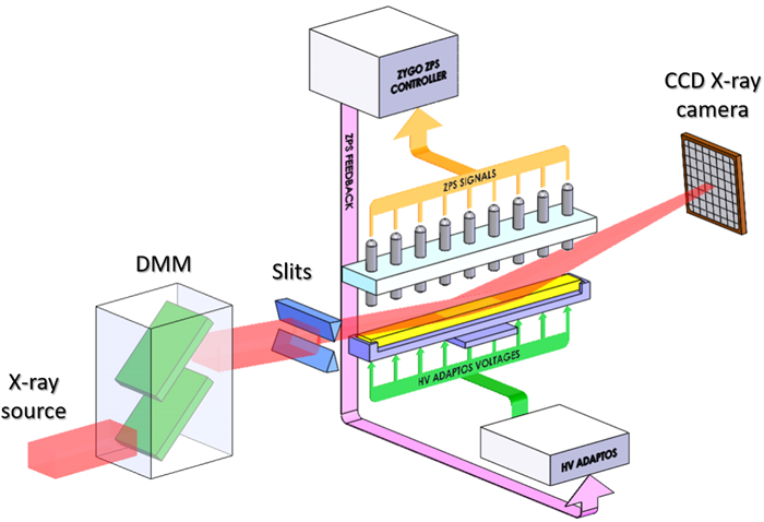
Fig. 3. Schematic of the closed-loop bimorph apparatus installed on the B16 Test beamline at Diamond for X-Ray testing. A double multilayer monochromator (DMM) selected the desired X-Ray wavelength from the polychromatic bending magnet source. Motorized slits defined the size of the X-Ray beam illuminating the bimorph mirror. X-rays reflected from the bimorph mirror were imaged using an X-Ray CCD camera. The array of ZPS interferometers non-invasively measured the optical surface of the bimorph mirror throughout X-Ray tests and stream data to the HV-ADAPTOS power supply to apply voltage correction to the bimorph mirror’s piezo actuators. Image Credit: Zygo Corporation
Optimizing the X-Ray Beam Profile
The local curvature of the X-Ray wavefront is directly measured by the X-Ray speckle scanning (XSS) method.32 This involves a focused X-Ray beam with a spherical wavefront, where the local radius of the curvature R is constant and matches the distance between the focus and the position of the detector.
To initiate optimization, the XSS method measured the reflected X-Ray wavefront while voltages were successively applied to each piezo. These piezo response functions (PRFs) quantify how adjusting the mirror’s shape changes the X-Ray wavefront.
Utilizing the X-Ray PRFs and the wavefront error, voltages were iteratively calculated and applied to bend the mirror to optimally focus the X-Ray beam at the position of the detector.33 This technique additionally corrects wavefront distortions produced by other nonperfect optics, including the DMM, located upstream of the bimorph mirror.
Indirect and Non-Invasive Control of X-Ray Wavefront
Different variations of sensors are employed to monitor X-Ray beams at XFEL and synchrotron sources and guide the alignment and curvature optimization of active mirrors to attain the desired wavefront.34–36
Preferably, such sensors should be non-invasive and not lead to appreciable attenuation or distortion to the X-Ray beam. This allows the transmitted X-Ray beam to be continuously and efficiently utilized for scientific research.
Non-invasive sensors are available;37 however, they do not possess the spatial or phase sensitivity required for the accurate characterization of X-Ray wavefronts. Alternate diagnostic instruments that have the required spatial sensitivity are invasive and/or require many seconds or minutes to record the wavefront.
At present, no commercially available sensor can simultaneously deliver real-time, non-invasive measurement of the X-Ray wavefront with adequate spatial sensitivity to attain diffraction-limited performance.16,38
To alleviate this problem, a two-step process is proposed. To begin with, the X-Ray wavefront is characterized via XSS and corrected to the desired profile utilizing the PRF and inverse-matrix technique described above. The ZPS sensors then subsequently record the X-Ray mirror’s shape - which generates the required reflected X-Ray wavefront.
This process of calibration is repeated for multiple desired X-Ray wavefronts, including the production of a focused X-Ray beam and a set of flattop intensity profiles.
After the X-Ray wavefront sensor is removed from the beam path, the bimorph may be quickly driven to any pre-recorded target shape and instantly stabilized with sub-nm accuracy utilizing closed-loop feedback from the ZPS interferometric sensors.
If other components on the beamline are not drifting significantly, this scheme offers rapid, indirect, and non-invasive switching and control of the X-Ray wavefront.
Results
Curvature Drift of a Bimorph Mirror Operating in Open-Loop Mode
Dynamic drift of the curvature of the mirror is affected by numerous factors, such as hysteresis or strain from the mirror’s opto-mechanical holder that resists piezo bending, piezoelectric creep of the actuators, and differential thermal expansion between components due to ambient temperature changes.
The impact of the latter effect is typically negligible for optics operating in stable conditions under vacuum.
While the photon-induced heat bump is approximately constant in time at many facilities, this assumption cannot be guaranteed for advanced third- or fourth-generation light sources in the future. Figure 4 displays an example of parasitic curvature drift.
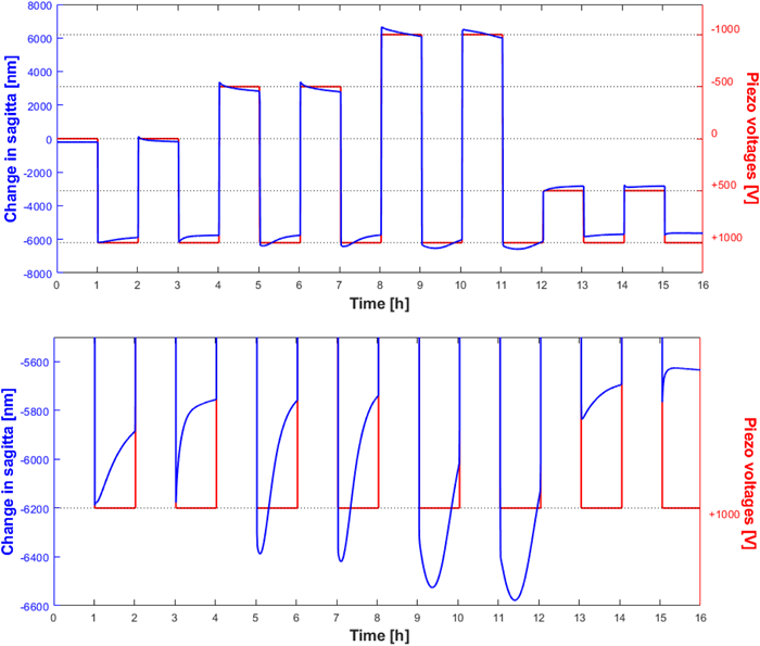
Fig. 4. Demonstration of variable sag changes caused by making major changes to the curvature of a bimorph X-Ray mirror operating in open loop. The upper chart shows the change in the sagitta of the mirror (blue curve and left-hand vertical axis), as measured by the ZPS interferometer system, as piezo voltages (red curve and right vertical axis) were cycled at hourly intervals. Starting from a very stable state of 0 V, at each odd-numbered hour, the mirror’s piezo voltages were returned to +1000 V from a range of different starting voltages. Ideally, after each large voltage transition, the mirror’s sagitta should exhibit a sharp, square-wave step. However, in the lower chart, showing a zoomed region of the upper chart, the mirror’s sagitta variably drifts by hundreds of nanometers on each return to the +1000 V state. Curvature drift degrades the focusing performance of the mirror and limits its usability for fast and accurate operation with X-Rays. Image Credit: Zygo Corporation
The change in “sagitta” or sag (defined as the depth at the center, relative to the two ends) of the bimorph mirror operating in open-loop mode was measured by the ZPS interferometers while sizable voltage jumps were set to take place at hourly intervals to create significant alterations in the mirror’s curvature.
Before the test began, the mirror was allowed to stabilize for many hours with no voltage applied to any electrodes. After one hour, a significant 1000-volt differential was applied to all piezo actuators to allow the mirror to bend cylindrically.
After two hours, all piezos were changed back to 0 volts. At three hours, all piezos were driven to 1000 volts again.
This process of driving the voltages away from the 1000 V set point and then returning one hour later was repeated for different voltage jump sizes (500, 1000, 1500, 2000 volts). This is demonstrated on the right-hand vertical axis of Figure 4.
The sagitta (displayed as the blue curve and left-hand vertical axis) should ideally exhibit a series of sharply defined, repeatable square-wave functions when the voltages are applied to the piezo electrodes (displayed as the red curve and right-hand vertical axis).
However, this is not the case, as can be seen in the bottom image in Figure 4, which displays a vertically zoomed plot of the mirror’s sagitta for several returns to 1000 volts.
After the first step change in curvature, subsequent steps have increasingly large drifts of up to 700 nm in the mirror’s sagitta that take many hours to settle.
This is particularly evident for the maximal voltage change of 2000 volts (corresponding to the full stroke of the mirror and a sagitta change of more than 12500 nm), where the drift of 700 nm relates to a 5 % error.
This is significantly greater than the typical procurement tolerance of less than 1 % error in the pre-polished radius of synchrotron X-Ray mirrors. The direction and magnitude of drift are heavily impacted by previous voltage settings applied over the recent few hours.
X-Ray Beam Drift Caused by a Bimorph Mirror Operating in Open-Loop Mode
To establish whether the magnitude and time scale of curvature drift of the bimorph mirror’s optical surface have a measurable influence on the focal X-Ray beam’s size, the X-Ray CCD camera was employed to continuously measure the temporal properties of the vertical profile of the X-Ray beam while the mirror was continually defocused and then refocused.
The bimorph mirror was driven in open-loop mode to the optimized focusing voltages from two distinct starting points: one starting point was with all piezos at 0 volts (i.e., already close to realizing focus), and another starting point immediately after a large +1000-volt shift had been applied to all piezos to induce curvature drift in the mirror.
The left image in Figure 5 demonstrates how the X-Ray beam was almost immediately focused and remained stable afterward when the mirror had only small voltage changes (tens of volts) applied.
In contrast, after applying a voltage change of 1000 volts before refocusing, the amplitude and width of the reflected X-Ray beam were not well optimized upon refocusing – as shown in the right image in Figure 5. The quality of the X-Ray beam gradually improved, but after five minutes, it was still not completely refocused.
Figure 6 quantifies the dynamic changes in the X-Ray beam size by plotting the FWHM vertical width of the X-Ray beam as a function of time after refocusing. A Lorentzian curve was fitted to eliminate the background photons in each CCD image. To obtain the FWHM, a Gaussian curve was fitted to the X-Ray peak.
Although drift will ultimately stabilize and the X-Ray beam will asymptotically move toward the focused profile, this study has demonstrated that open-loop operation of the mirror is not appropriate for reliably causing fast and large changes to the X-Ray beam without waiting for prolonged periods for stabilization to take place.
Closed-Loop Stabilization
To prove the superior performance of closed-loop control, a repeated sequence of voltages was applied to the mirror at intervals of 20 seconds to defocus and subsequently refocus the mirror three times.
Defocusing was accomplished by the concurrent application of a large differential of −1000 volts to all piezos with a quick 300 volts per second slew rate to substantially change the curvature of the mirror.
This process was first carried out with the bimorph mirror being operated in open-loop, and subsequently repeated afterward using closed-loop control.
Figure 7 presents sequential snapshots of the X-Ray beam profile 15 seconds after each focusing operation in open-loop (shown by red curves) or closed-loop (shown by blue curves).
As expected, significant drifts and sub-optimal focusing were seen for the fast, open-loop operation of the X-Ray bimorph mirror.
For many years, time-related drifts following a sizable change in curvature have challenged bimorph X-Ray mirrors and limited their usage to quasi-static operation.
However, when operating the mirror in closed-loop mode, it instantly and repeatedly regained perfect focus and remained extremely stable, even after purposefully driving the mirror to high voltages to defocus the X-Ray beam.
Closed-loop operation thus facilitates the full dynamic potential of bimorph mirrors and provides a significant improvement in the speed and stability of the X-Ray beam focal quality when rapid and substantial changes are demanded.
Before beamline installation took place, metrology tests in the OML confirmed that the shape of the bimorph in closed-loop mode did not display any deviation over many hours and was consistently stable at an unprecedented level for active X-Ray optics of less than 0.3 nm peak-to-valley (PV) compared to the given target shape.
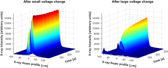
Fig. 5. Left image, CCD measurement of the vertical profile of the X-Ray beam as a function of time over a 5 min period after making small adjustments to the piezo voltages to optimally focus the bimorph mirror. The X-Ray beam is quickly focused and remains stable thereafter. Right image, a repeat of the focusing test, but with a +1000 V differential applied to all piezo actuators immediately before refocusing to purposefully induce a large curvature change in the mirror. In this instance, the X-Ray beam does not focus rapidly but slowly drifts toward its asymptotic shape. Even after 5 min, the X-Ray focus is still not optimized. This demonstrates that the bimorph mirror cannot reliably refocus in open loop after a large change is made to its curvature. Image Credit: Zygo Corporation
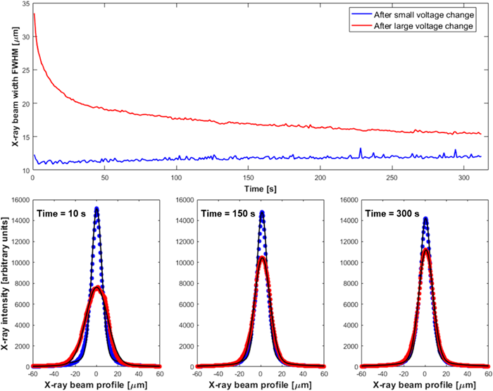
Fig. 6. The upper chart displays the dynamic progression of the full width at half-maximum (FWHM) of the vertical profile of the X-Ray beam during the focusing tests in Fig. 5. After a small voltage change to the bimorph (blue curve), the X-Ray beam is optimally focused within a few seconds and remains stable thereafter. However, after a large voltage change (red curve), the X-Ray beam takes many minutes to approach the optimal focus. The lower charts show corresponding temporal snapshots of the measured (black dots) and fitted (lines) cross-sectional profiles of the X-Ray beam after 10, 150, and 300 s for the different refocusing configurations. Image Credit: Zygo Corporation
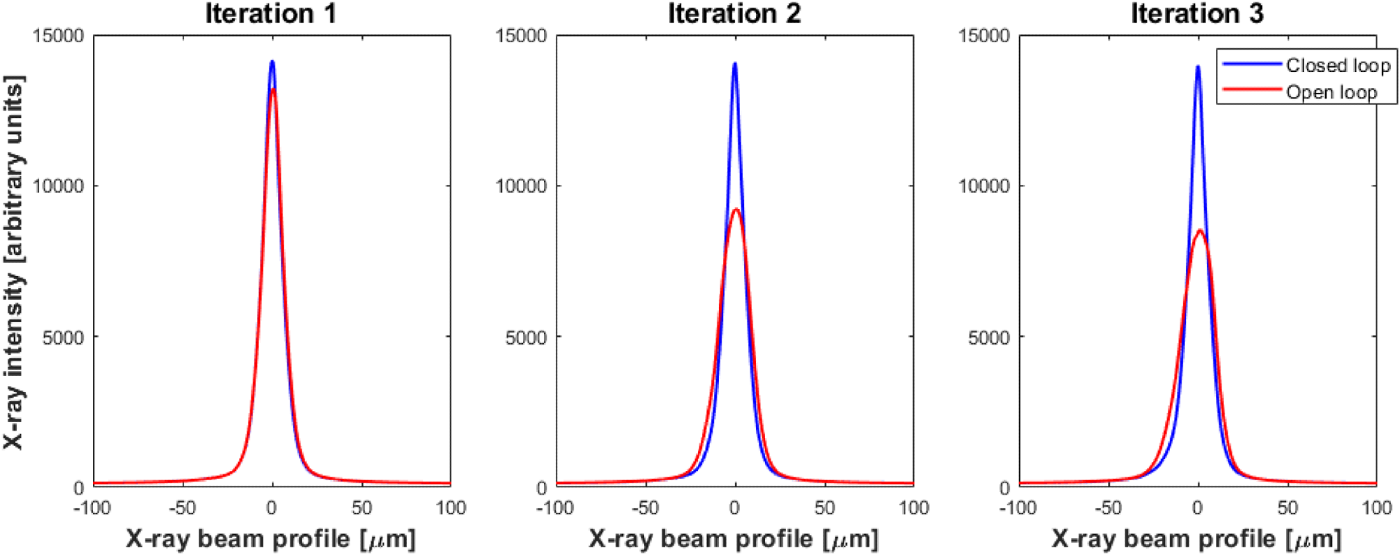
Fig. 7. To demonstrate the speed and accuracy of closed-loop control, the bimorph mirror was purposefully defocused and then refocused three times at 20 s intervals. Each image shows a temporal snapshot of the cross-sectional profile of the X-Ray beam 15 s after each iteration of refocusing. With closed-loop ZPS interferometer feedback of the bimorph mirror, the X-Ray focal spot was instantly stabilized (blue curves), even after a major change in the mirror’s curvature. Conversely, in open-loop (red curves), the mirror’s shape did not quickly return to the optimal focus. A video showing the time evolution of the X-Ray beam vertical profile is provided in Visualization 1. Image Credit: Zygo Corporation
Creating X-Ray Beams with a Flattop, Constant Intensity Profile
Although photon beam shaping with freeform optics is used regularly by multiple visible-light communities,39 it is particularly challenging and a novelty in the X-Ray domain.
However, the importance of beam shaping is growing at XFEL and synchrotron facilities,40 including converting Gaussian X-Ray beams (naturally produced by the source) into a constant intensity “top-hat” super-Gaussian profile of selectable width.
The X-Ray beam size typically ranges between < 100 nm and 150 µm and is selected to match the sample’s dimension or to attain a specific spatial resolution. Small amounts of deliberate defocusing can produce wider reflected X-Ray beams to probe greater regions of interest on the sample.
However, optical height errors as small as approximately 5 nm PV can introduce non-negligible intensity striations into out-of-focus X-Ray beams. An enhanced technique for producing higher-quality, flattop X-Ray profiles is the addition of parabolic segments of alternating convex and concave form to the optical surface.41
The additional degrees of bending freedom provided by a bimorph mirror allow the continuous range of higher-order, re-entrant surface profiles to generate X-Ray beams of user-defined width.42
The top image in Figure 8 displays the vertical profile of the X-Ray beam as a function of time, as recorded by the CCD camera, while the bimorph mirror was repeated through a series of shapes to either focus the X-Ray beam or generate flattop intensity profiles of differing widths.
X-Ray beam changes were cycled at intervals of 10 seconds in the following sequence: focus (approximately 12 µm FWHM), narrow flattop (approximately 55 µm FWHM), wide flattop (approximately 130 µm FWHM), and focus. The bottom image in Figure 8 shows time snapshots of the X-Ray beam profile during each of the three beam shapes.
There are intensity striations present that correlate to the imperfect polishing quality of this approximately 10-year-old bimorph mirror (with a slope error of approximately 500 nrad rms). The “narrow flattop” profile, corresponding to approximately 5× magnification of the X-Ray beam, displays striations that are less than 10 % of the peak intensity.
The pattern of striations on the wider flattop X-Ray beam is highly similar to that of the narrow flattop, but the former are laterally expanded.
This provides additional evidence that the striations derive from the inherent polishing errors of the mirror. Previous investigations revealed a strong correlation between the second spatial derivative of optical height errors and the resultant X-Ray beam striations.43–45
Additionally, the flattop beam’s congruent shape confirms that the piezoelectric actuator response is very close to ideal and is not creating further distortion to the optical surface.
Repolishing or replacing the mirror to a current state-of-the-art surface quality (with a slope error of < 100 nrad) would considerably reduce the number and amplitude of striations shown in the expanded X-Ray beam in Figure 8.
Splitting the X-Ray Beam into Multiple Controllable Peaks
Structured light is an area of renewed interest in many scientific fields.46 Bimorph mirrors allow the redistribution of the incident beam into a range of intensity distributions and even into multiple peaks without considerable loss of photon flux.
The X-Ray beam’s vertical intensity distribution, measured by the CCD camera, was separated into multiple peaks via a simple algorithm to divide the optical length of the biomorph mirror into sub-regions.
Each sub-region of the mirror was selected to focus a section of the X-Ray beam to a vertically displaced position in the focal plane. The user can control the spacing and relative amplitude of the reflected X-Ray peaks by careful consideration of the angle, length, and location of each sub-region of the mirror.
Beginning with a focused X-Ray beam (shown as the black curve), the left image in Figure 9 depicts the X-Ray beam split into two peaks (shown as the blue curve) separated by approximately 67 µm.
This was accomplished by the application of suitable voltages to the piezo electrodes based on the PRF data to adjust the amplitude of slope changes on the bimorph mirror.
The space between the two X-Ray peaks was subsequently increased to approximately 100 µm (red curve) by increasing the amplitude of the slope change. The orange and green curves shown in the right image of Figure 9 demonstrate how the relative intensity ratio of each peak in the wider beam splitter can be changed from 50:50 to approximately 65:35.
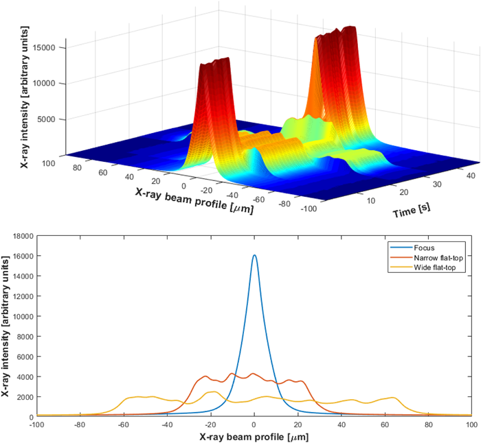
Fig. 8. Upper image, vertical profile of the X-Ray beam as a function of time, as the bimorph mirror was purposefully deformed under closed-loop control to quickly switch between either a focused beam or a constant intensity “flattop” profile of user-defined width. Lower image, super-imposed, time snapshots showing the focused X-Ray beam and flattop intensity profiles. A video showing the time evolution of the X-Ray beam is provided in Visualization 2. Image Credit: Zygo Corporation
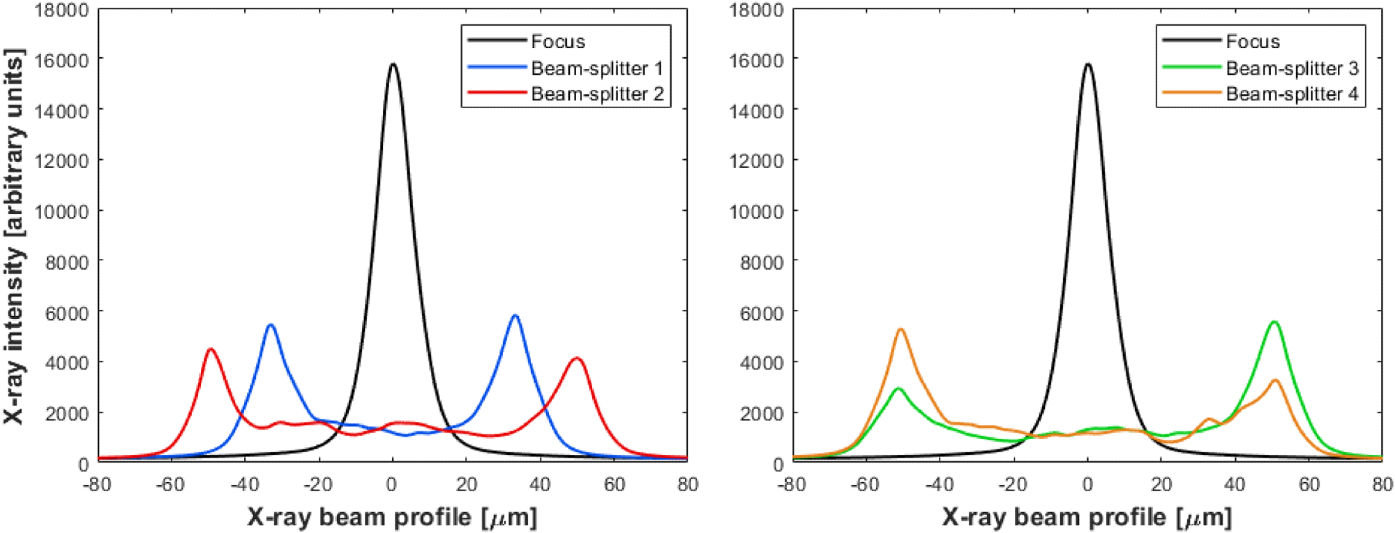
Fig. 9. Left image, overlaid X-Ray beam profiles, as measured by the CCD camera, showing how the focused X-Ray beam (black curve) can be split into two equal peaks (blue curve), without loss of flux, by applying localized slope changes to the bimorph mirror. The spacing between peaks can also be widened (red curve) by increasing the amplitude of slope changes applied to the mirror. Right image, the relative intensity of each X-Ray peak can be controlled (green and orange curves). A video showing the time evolution of the X-Ray beam is provided in Visualization 3. Image Credit: Zygo Corporation
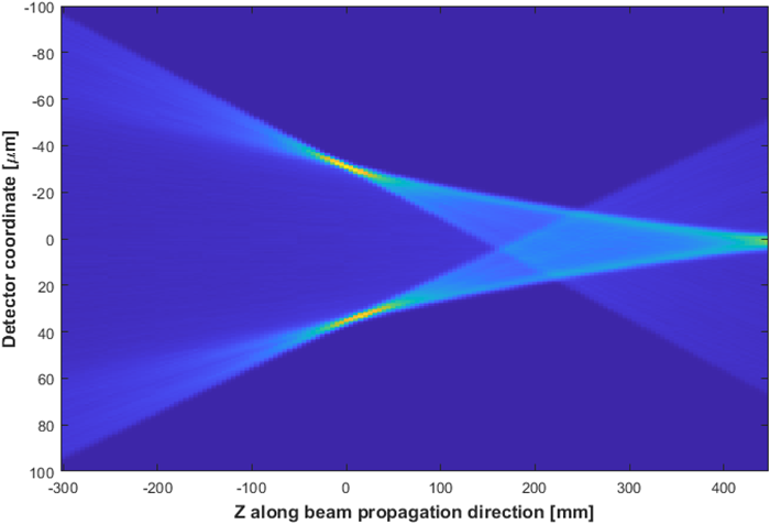
Fig. 10. Ray-tracing simulation illustrating how the split X-Ray peaks propagate along the beamline’s optical axis, Z. Each vertical slice shows the intensity profile predicted from theory to be recorded by the CCD camera located at each position Z along the length of the beamline. Note that the split peaks are optimized at the focal position where Z = 0. Image Credit: Zygo Corporation
Simulations of the Split X-Ray Beam Profile
To examine the propagation of the split X-Ray beam through the focal plane, a ray-tracing simulation was carried out using the XRT python package.47
As expected, Figure 10 hypothetically predicts that the maximum intensity and corresponding minimum peak width for the focal position, Z = 0, for both split peaks. The image was created by the integration of the X-Ray intensity along the detector’s horizontal plane.
Discussion and Future Outlook
The X-Ray beam’s cross-sectional profile and positional stability depend on the dynamic behavior of the X-Ray source as well as all optical components on the beamline.
The study described in this article did not aim to stabilize the X-Ray beam from all outside influences. Instead, it aimed to allow rapid and repeatable changes in the shape and size of the X-Ray beam utilizing a closed-loop, adaptive bimorph mirror.
The results of this study highlight that other beamline components were stable enough for the success of this scheme.
However, a more long-term goal is to utilize the full complement of up to 64 ZPS sensors to concurrently monitor and autonomously correct the linear and angular position of all beamline components, potentially employing schemes that leverage artificial intelligence.
This is a crucial part of Diamond’s strategy to realize real-time, autonomous control of micro- and nano-focused X-Ray beams with improved versatility and quality without the need for skilled operators.
Methodology and hardware can be applied to any deformable mirror, irrespective of the actuation method. The only required modification would be to calibrate the response functions of the new mirror to deliver accurate inputs to the correction algorithm.
Currently, the majority of synchrotrons operate in “top-up” mode, which involves the circulating electron current being quasi-continuously refilled to compensate for charge loss. This results in a nearly constant photon-induced heat load on many beamline optics.
However, new and upgraded XFEL and synchrotron light sources lead to an increased X-Ray flux density. This can result in a significant “heat-bump” on the primary optics, which distorts the reflected or diffracted X-Ray wavefront.
A key technical challenge is the identification of methods that efficiently cool these optics to minimize the scale of the distortion.
Adding a cooling manifold to the bimorph mirror (such as introducing copper cooling blades to conduct heat away without producing vibrations or adding grooves in the optical substrate that will be filled with Ga/In eutectic) could make the closed-loop control system a suitable method for automatically measuring and dynamically bending the bimorph mirror to cancel out the photon-induced heat bump.
This would enable the quick correction of wavefront distortions that are caused by time-dependent variations in the incident X-Ray flux.
If bimorph technology is not robust enough to withstand the extreme radiation and temperature environment, the ZPS system could offer feedback for a novel scheme48 by applying time-variable cooling to localized regions of the optic.
Conclusion
The study detailed in this article successfully demonstrated a closed-loop adaptive optical system that can quickly adjust and stabilize the shape of X-Ray beams at XFEL and synchrotron beamlines.
For the first time, an X-Ray bimorph mirror has been quickly driven and fixed at user-defined target shapes with sub-nanometer sensitivity based on interferometric feedback operating constantly at 1 Hz.
After sizable changes were made to the profile of the X-Ray beam, high-spatial order, time-varying distortions of the optical surface were rapidly nullified according to the ultra-stable reference plane of an array of ZPS distance-measuring sensors set in a decoupled metrology frame.
Following the initial X-Ray wavefront calibration, the invasive X-Ray sensor was removed from the path of the beam.
A straightforward, push-button, closed-loop control then allowed a non-specialist operator to rapidly alternate between various types of X-Ray wavefronts without the X-Ray beam being blocked or attenuated, thereby maximizing scientific productivity.
The indirect monitoring and control of the X-Ray wavefront introduces great potential for applications that demand quick and accurate changes in the shape and size of X-Ray beams.
This study demonstrates that this can produce non-Gaussian beams, including flattop intensity profiles or even multiple split peaks with user-controllable separation and relative amplitude.
This signifies a paradigm shift in the utilization of X-Ray bimorph mirrors at XFEL and synchrotron light sources as real-time “adaptive” optics, operating in a non-equilibrium, dynamic state. Ex-situ metrology did not detect any long-term damage to the bimorph mirror.
An example of an immediate application is serial crystallography, where various-sized samples are measured in rapid succession.
While this technology was developed to offer scientific gains for X-Ray science, it is anticipated that the rapid, nanoscale control of macroscopic adaptive optics will be of general interest to many more optical communities that need ultra-stability and maximum optical control.
Acknowledgments
Produced from materials originally authored by Simon G. Alcock,1 Ioana-Theodora Nistea,1 Vivek G. Badami,2 Riccardo Signorato,3 Matteo Fusco,4 Lingfei Hu,1 Hongchang Wang,1 and Kawal Sawhney.1
The original authors wish to thank Andrew Malandain and Oliver Fox for installing the bimorph mirror and Andrew Foster for developing EPICS communication protocols with the HV-ADAPTOS. They also wish to thank colleagues in the Optics & Metrology group, especially Hossein Khosroabadi, John Sutter, and Andrew Walters. They wish to acknowledge the work of Andrea Pezzini at CAEN for developing the HV-ADAPTOS hardware.
1Diamond Light Source Ltd, Didcot, UK; 2Zygo Corporation, Connecticut, USA; 3S.RI. Tech, Vigonza, Italy; 4CAEN, Viareggio, Italy.
References and Further Reading
- S. Matsuyama, T. Inoue, J. Yamada, J. Kim, H. Yumoto, Y. Inubushi, T. Osaka, I. Inoue, T. Koyama, K. Tono, H. Ohashi, M. Yabashi, T. Ishikawa, and K. Yamauchi, “Nanofocusing of X-Ray free-electron laser using wavefront-corrected multilayer focusing mirrors,” Sci. Rep. 8, 17440 (2018).
- C. Kettenbeil, J. Jewell, J. K. Wallace, and J. Steeves, “Picometer wavefront sensing using the phase-contrast technique,” Optica 7, 1267–1274 (2020).
- R. Signorato, “R&D program on multisegmented piezoelectric bimorph mirrors at the ESRF: status report,” Proc. SPIE 3447, 20–31 (1998).
- R. Signorato, “R&D program on multisegmented piezoelectric bimorph mirrors at the ESRF–status report: II,” Proc. SPIE 3773, 50–59 (1999).
- R. Signorato and T. Ishikawa, “R&D on third generation multi-segmented piezoelectric bimorph mirror substrates at Spring-8,” Nucl. Instrum. Methods Phys. Res. A 467–468, 271–274 (2001).
- A. Erko, F. Schäfers, A. Firsov, W. B. Peatman, W. Eberhardt, and R. Signorato, “The BESSY X-Ray microfocus beamline project,” Spectrochim. Acta B Atom. Spectros. 59, 1543–1548 (2004).
- R. Signorato, D. Hausermann, M. Somayazulu, and J.-F. Carré, “Performance of an adaptive u-focusing Kirkpatrick-Baez system for high-pressure studies at the Advanced Photon Source,” Proc. SPIE 5193, 112–123 (2004).
- S. Matsuyama, H. Nakamori, T. Goto, T. Kimura, K. P. Khakurel, Y. Kohmura, Y. Sano, M. Yabashi, T. Ishikawa, Y. Nishino, and K. Yamauchi, “Nearly diffraction-limited X-Ray focusing with variable-numerical aperture focusing optical system based on four deformable mirrors,” Sci. Rep. 6, 24801 (2016).
- J. P. Sutter, S. G. Alcock, I. T. Nistea, H. Wang, and K. Sawhney, “Active and adaptive X-Ray optics at diamond light source,” Synchrotron. Radiat. News 35(2), 8–13 (2022).
- “Diamond light source,” https://www.diamond.ac.uk.
- M. Vannoni, I. Freijo Martín, and H. Sinn, “Characterization of an X-Ray mirror mechanical bender for the European XFEL,” J. Synchrotron. Radiat. 23, 855–860 (2016).
- M. Sanchez Del Rio, A. Wojdyla, K. A. Goldberg, G. D. Cutler, D. Cocco, and H. A. Padmore, “Compensation of heat load deformations using adaptive optics for the ALS upgrade: a wave optics study,” J. Synchrotron Rad. 27, 1141–1152 (2020).
- L. Huang, J. Xue, and M. Idir, “Controlling X-Ray deformable mirrors during inspection,” J. Synchrotron Rad. 23, 1348–1356 (2016).
- M. Vannoni, I. F. Martín, V. Music, and H. Sinn, “Calibration and optimization of an X-Ray bendable mirror using displacement-measuring sensors,” Opt. Express 24, 17292–17302 (2016).
- K. Sawhney, S. Alcock, J. Sutter, S. Berujon, H. Wang, and R. Signorato, “Characterisation of a novel super-polished bimorph mirror,” J. Phys. Conf. Ser. 425, 052026 (2013).
- D. Cocco, G. Cutler, M. Sanchez del Rio, L. Rebuffi, X. Shi, and K. Yamauchi, “Wavefront preserving X-Ray optics for synchrotron and free electron laser photon beam transport systems,” Phys. Rep. 974, 1–40 (2022).
- S. G. Alcock, J. P. Sutter, K. J. S. Sawhney, D. R. Hall, K. McAuley, and T. Sorensen, “Bimorph mirrors: the good, the bad, and the ugly,” Nucl. Instrum. Methods Phys. Res. A 710, 87–92 (2013).
- J.-F. Carré, “Bimorph optical element,” U.S. patent 8469527 (25 June 2013). Research Article Vol. 10, No. 2 / February 2023 / Optica 182
- S. G. Alcock, I. Nistea, J. P. Sutter, K. Sawhney, J. J. Fermé, C. Thellièr, and L. Peverini, “Characterization of a next-generation piezo bimorph xray mirror for synchrotron beamlines,” J. Synchrotron Radiat. 22, 10–15 (2015).
- S. G. Alcock, I.-T. Nistea, R. Signorato, and K. Sawhney, “Dynamic adaptive X-Ray optics. Part I. Time-resolved optical metrology investigation of the bending behaviour of piezoelectric bimorph deformable X-Ray mirrors,” J. Synchrotron Radiat. 26, 36–44 (2019).
- L. A. Poyneer, T. Pardini, T. McCarville, D. Palmer, and A. Brooks, “Control of a 45-cm long X-Ray deformable mirror with either external or internal metrology,” Proc. SPIE 9208, 92080F (2014).
- M. Vannoni, I. F. Martín, S. Smidtchen, T. M. Baumann, M. Meyer, and V. Music, “Metrology characterization of ultraprecise bendable mirrors for the European XFEL: from offsite calibration to installation and commissioning,” J. Synchrotron Radiat. 26, 1110–1114 (2019).
- S. G. Alcock, I. T. Nistea, V. G. Badami, R. Signorato, and K. Sawhney, “High-speed adaptive optics using bimorph deformable X-Ray mirrors,” Rev. Sci. Instrum. 90, 021712 (2019).
- V. G. Badami, E. Abruña, L. Huang, and M. Idir, “In situ metrology for adaptive X-Ray optics with an absolute distance measuring sensor array,” Rev. Sci. Instrum. 90, 021703 (2019).
- I.-T. Nistea, S. G. Alcock, V. Badami, R. Signorato, and K. J. S. Sawhney, “Controlling an active bimorph deformable mirror with sub-nanometre resolution,” Proc. SPIE 11109, 111090E (2019).
- I.-T. Nistea, S. G. Alcock, M. Bazan da Silva, and K. J. S. Sawhney, “The optical metrology laboratory at diamond: pushing the limits of nano-metrology,” Proc. SPIE 11109, 1110906 (2019).
- “EPICS 7 Core Status Report,” https://www.researchgate.net/ publication/336567873_EPICS_7_Core_Status_Report.
- S. G. Alcock, I. T. Nistea, R. Signorato, R. L. Owen, D. Axford, J. P. Sutter, A. Foster, and K. Sawhney, “Dynamic adaptive X-Ray optics. Part II. High-speed piezoelectric bimorph deformable Kirkpatrick–Baez mirrors for rapid variation of the 2D size and shape of X-Ray beams,” J. Synchrotron Radiat. 26, 45–51 (2019).
- K. J. S. Sawhney, I. P. Dolbnya, M. K. Tiwari, L. Alianelli, S. M. Scott, G. M. Preece, U. K. Pedersen, and R. D. Walton, “A test beamline on diamond light source,” AIP Conf. Proc. 1234, 387–390 (2010).
- H. Wang, J. Sutter, and K. Sawhney, “Advanced in situ metrology for X-Ray beam shaping with super precision,” Opt. Express 23, 1605–1614 (2015).
- H. Wang, K. Sawhney, S. Berujon, J. Sutter, S. G. Alcock, U. Wagner, and C. Rau, “Fast optimization of a bimorph mirror using X-Ray grating interferometry,” Opt. Lett. 39, 2518–2521 (2014).
- M. Idir, D. Cocco, and L. Huang, “Special issue ‘EUV and X-Ray wavefront sensing’,” Sensors 22, 3940–3943 (2022).
- H. J. Lee, Y. Feng, G. Marcus, D. Zhu, D. Cocco, M. Seaberg, A. Aquila, J. Krzywinski, B. Nagler, C. Hardin, A. Sakdinawat, F. Seiboth, S. Boutet, Y. Liu, and Y. Ding, “High-accuracy wavefront sensing for X-Ray free electron lasers,” Optica 5, 967–975 (2018).
- M. Seaberg, R. Cojocaru, S. Berujon, et al., “Wavefront sensing at X-Ray free-electron lasers,” J. Synchrotron Radiat. 26, 1115–1126 (2019).
- K. A. Goldberg, A. Wojdyla, and D. Bryant, “Binary amplitude reflection gratings for X-Ray shearing and Hartmann wavefront sensors,” Sensors 21, 536 (2021).
- H. Wang, K. Sawhney, L. Hu, and O. Fox, “Fast wavefront sensing for xray optics with an alternating speckle tracking technique,” Opt. Express 30, 33259–33273 (2022).
- J. P. Rolland, M. A. Davies, T. J. Suleski, C. Evans, A. Bauer, J. C. Lambropoulos, and K. Falaggis, “Freeform optics for imaging,” Optica 8, 161–176 (2021).
- D. Spiga, L. Raimondi, C. Svetina, and M. Zangrando, “X-Ray beamshaping via deformable mirrors: analytical computation of the required mirror profile,” Nucl. Instrum. Methods Phys. Res. A 710, 125–130 (2013).
- D. Laundy, K. Sawhney, I. Nistea, S. G. Alcock, I. Pape, J. Sutter, L. Alianelli, and G. Evans, “Development of a multi-lane X-Ray mirror providing variable beam sizes,” Rev. Sci. Instrum. 87, 051802 (2016).
- J. P. Sutter, S. G. Alcock, Y. Kashyap, I. Nistea, H. Wang, and K. Sawhney, “Creating flat-top X-Ray beams by applying surface profiles of alternating curvature to deformable piezo bimorph mirrors,” J. Synchrotron Radiat. 23, 1333–1347 (2016).
- J. P. Sutter, S. G. Alcock, F. Rust, H. Wang, and K. Sawhney, “Structure in defocused beams of X-Ray mirrors: causes and possible solutions,” Proc. SPIE 9208, 92080G (2014).
- L. Hu, H. Wang, J. P. Sutter, and K. Sawhney, “Investigation of the stripe patterns from X-Ray reflection optics,” Opt. Express 29, 4270–4286 (2021).
- D. Cocco and D. Spiga, “Wavefront preserving optics for diffraction limited storage rings and free-electron lasers,” Proc. SPIE 11111, 37–46 (2019).
- A. Forbes, M. de Oliveira, and M. R. Dennis, “Structured light,” Nat. Photonics 15, 253–262 (2021).
- K. Klementiev and R. Chernikov, “Powerful scriptable ray tracing package XRT,” Proc. SPIE 9209, 60–75 (2014).
- D. Cocco, D. Cocco, C. Hardin, D. Morton, L. Lee, M. L. Ng, L. Zhang, L. Assoufid, W. Grizolli, X. Shi, D. A. Walko, G. Cutler, K. A. Goldberg, A. Wojdyla, M. Idir, L. Huang, and G. Dovillaire, “Adaptive shape control of wavefront-preserving X-Ray mirrors with active cooling and heating,” Opt. Express 28, 19242–19254 (2020).

This information has been sourced, reviewed and adapted from materials provided by Zygo Corporation.
For more information on this source, please visit Zygo Corporation.